Transcription of J111, J112 - JFET Chopper Transistors
1 Semiconductor Components Industries, LLC, 2006 March, 2006 Rev. 21 Publication Order Number:J111/DJ111, J112 jfet Chopper TransistorsN channel DepletionFeatures Pb Free Packages are Available*MAXIMUM RATINGSR atingSymbolValueUnitDrain Gate VoltageVDG 35 VdcGate Source VoltageVGS 35 VdcGate CurrentIG50mAdcTotal Device Dissipation @ TA = 25 CDerate above = 25 CLead TemperatureTL300 COperating and Storage JunctionTemperature RangeTJ, Tstg 65 to +150 CMaximum ratings are those values beyond which device damage can ratings applied to the device are individual stress limit values (notnormal operating conditions) and are not valid simultaneously. If these limits areexceeded, device functional operation is not implied, damage may occur andreliability may be affected.
2 *For additional information on our Pb Free strategy and soldering details, pleasedownload the ON Semiconductor Soldering and Mounting TechniquesReference Manual, 92 CASE 29 11 STYLE 5123J11xAYWWGG1 DRAIN2 SOURCE3 GATESee detailed ordering and shipping information in the packagedimensions section on page 2 of this data INFORMATIONJ11x = Device Codex = 1 or 2A= Assembly LocationY= YearWW = Work WeekG= Pb Free Package(Note: Microdot may be in either location)J111, J112 CHARACTERISTICS (TA = 25 C unless otherwise noted)CharacteristicSymbolMinMaxUnitOFF CHARACTERISTICSGate Source Breakdown Voltage(IG = mAdc)V(BR)GSS35 VdcGate Reverse Current(VGS = 15 Vdc)IGSS Source Cutoff Voltage(VDS = Vdc, ID = mAdc)J111J112 VGS(off) 10 Cutoff Current(VDS = Vdc, VGS = 10 Vdc)ID(off) CHARACTERISTICSZero Gate Voltage Drain Current(1)(VDS = 15 Vdc) mAdcStatic Drain Source On Resistance(VDS = Vdc)J111J112rDS(on) 3050 WDrain Gate and Source Gate On Capacitance(VDS = VGS = 0, f = MHz)Cdg(on)+Csg(on) 28pFDrain Gate Off Capacitance(VGS = 10 Vdc, f = MHz)Cdg(off) Gate Off Capacitance(VGS = 10 Vdc, f = MHz)Csg(off)
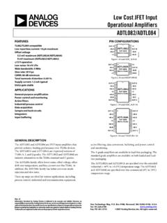
3 Pulse Width = 300 ms, Duty Cycle = INFORMATIOND evicePackageShipping J111RL1TO 922000 Units / Tape & ReelJ111RL1 GTO 92(Pb Free)J111 RLRATO 922000 Units / Tape & ReelJ111 RLRAGTO 92(Pb Free)J111 RLRPTO 922000 Units / Tape & ReelJ111 RLRPGTO 92(Pb Free)J112TO 921000 Units / BulkJ112 GTO 92(Pb Free)J112RL1TO 922000 Units / Tape & ReelJ112RL1 GTO 92(Pb Free)J112 RLRATO 922000 Units / Tape & ReelJ112 RLRAGTO 92(Pb Free) For information on tape and reel specifications, including part orientation and tape sizes, please refer to our Tape and Reel PackagingSpecifications Brochure, BRD8011 , J112 , FALL TIME (ns)tr, RISE TIME (ns)td(on), TURN ON DELAY TIME (ns) , DRAIN CURRENT (mA)Figure 1.
4 Turn On Delay TimeRK = 0TJ = 25 CJ111J112J113 VGS(off) = 12 V= V= VRK = RD , DRAIN CURRENT (mA)Figure 2. Rise TimeRK = RD RK = 0TJ = 25 CJ111J112J113 VGS(off) = 12 V= V= , DRAIN CURRENT (mA)Figure 3. Turn Off Delay TimeRK = RD RK = 0TJ = 25 CJ111J112J113 VGS(off) = 12 V= V= Vtd(off), TURN OFF DELAY TIME (ns) , DRAIN CURRENT (mA)Figure 4. Fall TimeRK = RD RK = 0TJ = 25 CJ111J112J113 VGS(off) = 12 V= V= VTYPICAL SWITCHING CHARACTERISTICSNOTE 1 The switching characteristics shown above were measured using a testcircuit similar to Figure 5. At the beginning of the switching interval,the gate voltage is at Gate Supply Voltage ( VGG). The Drain SourceVoltage (VDS) is slightly lower than Drain Supply Voltage (VDD) dueto the voltage divider.
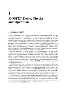
5 Thus Reverse Transfer Capacitance (Crss) orGate Drain Capacitance (Cgd) is charged to VGG + the turn on interval, Gate Source Capacitance (Cgs)discharges through the series combination of RGen and RK. Cgd mustdischarge to VDS(on) through RG and RK in series with the parallelcombination of effective load impedance (R D) and Drain SourceResistance (rds). During the turn off, this charge flow is turn on time is somewhat difficult as the channel resistancerds is a function of the gate source voltage. While Cgs discharges, VGSapproaches zero and rds decreases. Since Cgd discharges through rds,turn on time is non linear. During turn off, the situation is reversedwith rds increasing as Cgd above switching curves show two impedance conditions; 1) RKis equal to RD, which simulates the switching behavior of cascadedstages where the driving source impedance is normally the loadimpedance of the previous stage, and 2) RK = 0 (low impedance) thedriving source impedance is that of the WVGENINPUTRK50 WRGGVGG50 WOUTPUTRD+VDDRTSET VDS(off) = 10 VINPUT PULSE trtfPULSE WIDTHDUTY CYCLE ns ns= ms & RKRD +RD(RT)50)RD)RT)50 Figure 5.
6 Switching Time Test CircuitJ111, J112 (on), DRAIN SOURCE ON STATERESISTANCE (OHMS)NOTE 2 The Zero Gate Voltage Drain Current (IDSS), is theprinciple determinant of other J-FET 10 shows the relationship of Gate Source OffVoltage (VGS(off) and Drain Source On Resistance(rds(on)) to IDSS. Most of the devices will be within 10%of the values shown in Figure 10. This data will be usefulin predicting the characteristic variations for a given example:Unknownrds(on) and VGS range for an J112 The electrical characteristics table indicates that an J112has an IDSS range of 25 to 75 mA. Figure 10, showsrds(on) = 52 W for IDSS = 25 mA and 30 W forIDSS = 75 mA. The corresponding VGS values are Vand , FORWARD TRANSFER ADMITTANCE (mmhoC, CAPACITANCE (pF)rds(on), DRAIN SOURCE ON STATERESISTANCE (OHMS)rds(on), DRAIN SOURCE ON STATERESISTANCE (NORMALIZED) 10203050ID, DRAIN CURRENT (mA)Figure 6.))
7 Typical Forward Transfer , REVERSE VOLTAGE (VOLTS)Figure 7. Typical , GATE SOURCE VOLTAGE (VOLTS)Figure 8. Effect of Gate Source VoltageOn Drain Source 70 40 10205080110140170 Tchannel, channel TEMPERATURE ( C)Figure 9. Effect of Temperature OnDrain Source On State ResistanceJ113J112J111 Tchannel = 25 CVDS = 15 VCgsCgdTchannel = 25 C(Cds IS NEGLIGIBLE)IDSS= 10mA25mA50 mA75 mA100 mA125 mATchannel = 25 CID = mAVGS = 010 IDSS, ZERO GATE VOLTAGE DRAIN CURRENT (mA)Figure 10. Effect of IDSS On Drain SourceResistance and Gate Source Voltage20 3040 50 60708090100110 120 130 140 , GATE SOURCE VOLTAGE (VOLTS)Tchannel = 25 CrDS(on) @ VGS = 0 VGS(off)TO 92 (TO 226)CASE 29 11 ISSUE AMDATE 09 MAR 2007 STYLES ON PAGE 2 NOTES:1.
8 DIMENSIONING AND TOLERANCING PER , CONTROLLING DIMENSION: CONTOUR OF PACKAGE BEYOND DIMENSION RIS LEAD DIMENSION IS UNCONTROLLED IN P ANDBEYOND DIMENSION K X XCVDNNXXSEATINGPLANEDIM MINMAXMIN 1:112312 BENT LEADTAPE & REELAMMO PACKSTRAIGHT LEADBULK PACK3 NOTES:1. DIMENSIONING AND TOLERANCING PERASME , CONTROLLING DIMENSION: CONTOUR OF PACKAGE BEYONDDIMENSION R IS LEAD DIMENSION IS UNCONTROLLED IN PAND BEYOND DIMENSION K X XCVDNXXSEATINGPLANEDIM LEADBULK PACKBENT LEADTAPE & REELAMMO PACKMECHANICAL CASE OUTLINEPACKAGE Semiconductor Components Industries, LLC, 2002 October, 2002 Rev. 0 Case Outline Number:XXXDOCUMENT NUMBER:STATUS:NEW STANDARD:DESCRIPTION:98 ASB42022 BON SEMICONDUCTOR STANDARDTO 92 (TO 226)Electronic versions are uncontrolled except when accessed directly from the Document Repository.
9 Printed versions are uncontrolled except when stamped CONTROLLED COPY in 1 OF 3TO 92 (TO 226)CASE 29 11 ISSUE AMDATE 09 MAR 2007 STYLE 1:PIN 1. EMITTER2. BASE3. COLLECTORSTYLE 6:PIN 1. GATE2. SOURCE & SUBSTRATE3. DRAINSTYLE 11:PIN 1. ANODE2. CATHODE & ANODE3. CATHODESTYLE 16:PIN 1. ANODE2. GATE3. CATHODESTYLE 21:PIN 1. COLLECTOR2. EMITTER3. BASESTYLE 26:PIN 1. VCC2. GROUND 23. OUTPUTSTYLE 31:PIN 1. GATE2. DRAIN3. SOURCESTYLE 2:PIN 1. BASE2. EMITTER3. COLLECTORSTYLE 7:PIN 1. SOURCE2. DRAIN3. GATESTYLE 12:PIN 1. MAIN TERMINAL 12. GATE3. MAIN TERMINAL 2 STYLE 17:PIN 1. COLLECTOR2. BASE3. EMITTERSTYLE 22:PIN 1.
10 SOURCE2. GATE3. DRAINSTYLE 27:PIN 1. MT2. SUBSTRATE3. MTSTYLE 32:PIN 1. BASE2. COLLECTOR3. EMITTERSTYLE 3:PIN 1. ANODE2. ANODE3. CATHODESTYLE 8:PIN 1. DRAIN2. GATE3. SOURCE & SUBSTRATESTYLE 13:PIN 1. ANODE 12. GATE3. CATHODE 2 STYLE 18:PIN 1. ANODE2. CATHODE3. NOT CONNECTEDSTYLE 23:PIN 1. GATE2. SOURCE3. DRAINSTYLE 28:PIN 1. CATHODE2. ANODE3. GATESTYLE 33:PIN 1. RETURN2. INPUT3. OUTPUTSTYLE 4:PIN 1. CATHODE2. CATHODE3. ANODESTYLE 9:PIN 1. BASE 12. EMITTER3. BASE 2 STYLE 14:PIN 1. EMITTER2. COLLECTOR3. BASESTYLE 19:PIN 1. GATE2. ANODE3. CATHODESTYLE 24:PIN 1. EMITTER2. COLLECTOR/ANODE3. CATHODESTYLE 29:PIN 1.