Example: quiz answers
Linear Regulator IC Series Linear Regulator 기초
그림에서는 pch mosfet 로 구성되어 있습니다만, nch mosfet 은 물론, pnp/npn 의 바이폴라 트랜지스터도 사용됩니다. 동작은 완전한 아날로그입니다. op amp 를 사용한 기본적인 제어회로의 하나인 귀환루프 회로로 제어되고 있습니다.
Tags:
Information
Domain:
Source:
Link to this page:
Documents from same domain
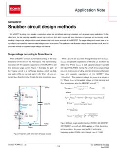
Snubber circuit design methods - Rohm
fscdn.rohm.comis bulk capacitor placed in parallel with input HVdc-PGND. During the turn off of LS, surge voltage occurs in drain-source of LS by resonant phenomenon between L MAIN and parasitic capacitance of the MOSFET C OSS ( C DS + DG). The maximum voltage V DS_SURGE is as shown in (1). Where V HVDC is the applied voltage on HVdc terminal and R OFF
SiC Power Devices and Modues Application Note
fscdn.rohm.com600V 400V 100V Si C D D D D G2GG 3ÿ G2GG H 9×3ÿ FÜ SiFÜ 8 æ GG ö G ì e Majority carrier device : High speed Minority carrier device : Low on-resistance, but low speed ・ Significant reduction in recovery loss ・ Downsizing of devices by increase in frequency Can be manufactured in this area, but little advantage over Si
Op-Amp/Comparator Application Note - Rohm
fscdn.rohm.comop-amp. Generally, an op-amp is composed of three stages: the input stage, the gain stage, and the output stage. The input stage is configured with a differential amplification stage that amplifies the differential voltage between the two terminals. In addition, it does not amplify the common-mode signal component (a condition where no ...
Efficiency of Buck Converter
fscdn.rohm.comEfficiency of Buck Converter Switching regulators are known as being highly efficient power sources. To further improve their efficiency, it is helpful to understand the basic mechanism of power loss. This application note explains power loss factors and methods for calculating them.
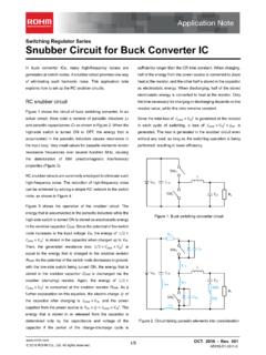
Snubber Circuit for Buck Converter IC : Power Management
fscdn.rohm.comSnubber Circuit for Buck Converter IC AEK59-D1-0311-0 For example, when the input voltage VIN is 24 V and the switching frequency fSW is 1 MHz, 2 Ë Ì Ç » L680 pF H24 6 H1 MHz L0.39 W the generated consumption power of 0.39 W requires a 6432 size resistor (2512 in inches) with a rated power of 1 W.
ISO 26262: Functional Safety Standard for Modern Road …
fscdn.rohm.comIntrinsic safety is a method for ensuring safety by removing the causes of danger. Functional safety, on the other hand, is a method of reducing risks to an acceptable level to ensure safety ... verification, prototyping, and evaluation are clarified, with reviews performed at each stage. It is also necessary to manage the documents created at
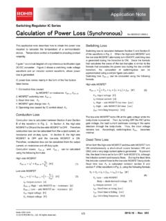
Calculation of Power Loss (Synchronous) : Power Management
fscdn.rohm.comCalculation of Power Loss (Synchronous) This application note describes how to obtain the power loss required to calculate the temperature of a semiconductor device. Temperature control is important to ensuring product reliability. Figure 1 is a circuit diagram of a synchronous rectification type DC/DC converter. Figure 2 shows a switching node ...
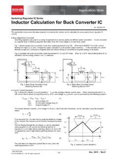
Inductor Calculation for Buck Converter IC
fscdn.rohm.comInductor Calculation of Buck Converter Current-difference between max. and min. (ILP-ILT) is as follows: IN SW D SW IN SW OUT D OUT LP LT V V V L f V V V V V I I (15) Equations (13) and (15) show that large inductance L and high switching frequency will reduce maximum current (ILP)and current difference between max. and min. (ILP-ILT).
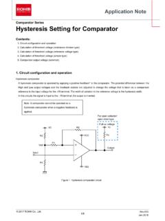
Hysteresis Setting for Comparator - Rohm
fscdn.rohm.comprovided only to illustrate the standard usage and operations of the Products. The peripheral conditions must be taken into account when designing circuits for mass production. The technical information specified herein is intended only to show the typical functions of and examples of application circuits for the Products.

ROHM Switching Regulator Solutions Synchronous Buck ...
fscdn.rohm.comROHM Switching Regulator Solutions Synchronous Buck Converter Controller BD9611MUV-EVK-001 Description Using a synchronous rectified step-down DC/DC converter IC BD9611MUV BD 9611MUV-EVK-001 evaluation board 15.0 V ~ output a 24 V input voltage 12.0 V. Provides 10.0A output current. Output current is possible with current settings by selecting
Related documents

MOSトランジスタの信頼性モデリング
kobaweb.ei.st.gunma-u.ac.jp•高温状態で,MOSFETのゲート電圧が負にバ イアスされて起きるので,Pch-MOSFETで発生 •しきい値電圧増加→ドレイン電流,伝達コンダ クタンス低下 •加速条件:温度=100~250℃,酸化膜電界= 6 MV/cm以下 •ゲートに正電圧の場合:P(Positive) BTIであり, Nch ...

スィッチング電源の基礎と応用 - Gunma U
kobaweb.ei.st.gunma-u.ac.jpパワーMOSFET IGBT: Insulated Gate Bipolar TRS (絶縁ゲートバイポーラトランジスタ) ・尐数キャリア蓄積効果 ・電流制御デバイス (オン抵抗小、遅延大) ・バイポーラ複合デバイス ・低周波、大電力 ・電圧制御デバイス ・キャリア蓄積なし (高速スイッチング)

DC/DCコンバータ設計セミナー - ROHM
pages.rohm.co.jp• pch/nch mosfetはさらに低ドロップ アウトを目指したもの + - v in v o v ref r 2 r 1 (=v ref) 制御トランジスタ ドロップアウト電 npn標準型 3v前後 npn ldo 1v~2v pnp ldo 0.5v以下 …