Transcription of LTC4441/LTC4441-1 - N-Channel MOSFET Gate Driver
1 LTC4441/LTC4441-1144411faTypical applicaTion FeaTuresDescripTionN-Channel MOSFET Gate DriverThe LTC 4441/LTC4441-1 is an N-Channel MOSFET gate Driver that can supply up to 6A of peak output current. The chip is designed to operate with a supply voltage of up to 25V and has an adjustable linear regulator for the gate drive. The gate drive voltage can be programmed between 5V and LTC4441/LTC4441-1 features a logic threshold Driver input. This input can be driven below ground or above the Driver supply. A dual function control input is provided to disable the Driver or to force the chip into shutdown mode with <12 A of supply current. Undervoltage lockout and overtemperature protection circuits will disable the Driver output when activated.
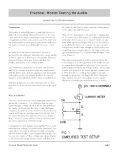
2 The LTC4441 also comes with an open-drain output that provides adjustable leading edge blanking to prevent ringing when sensing the source cur-rent of the power LTC4441 is available in a thermally enhanced 10-lead MSOP package. The LTC4441-1 is the SO-8 version without the blanking , LT, LTC, LTM, Linear Technology and the Linear logo are registered trademarks of Linear Technology Corporation. All other trademarks are the property of their respective owners. Protected by Patents including 6677210. RISE/FALL Time vs CLOAD applicaTionsn 6A Peak Output Currentn Wide VIN Supply Range: 5V to 25Vn Adjustable Gate Drive Voltage: 5V to 8Vn Logic Input Can Be Driven Below Groundn 30ns Propagation Delayn Supply Independent CMOS/TTL Input Thresholdsn Undervoltage Lockoutn Low Shutdown Current.
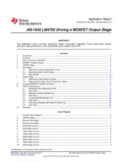
3 <12 An Overtemperature Protectionn Adjustable Blanking Time for MOSFET s Current Sense Signal (LTC4441)n Available in SO-8 and 10-Lead MSOP (Exposed Pad) Packagesn Power Suppliesn Motor/Relay Controln Line Driversn Charge Pumps+ TA01aR8511kR7R1330kR5 SHUTDOWNVIN6V TO 24 VSGNDCVCC10 FX5RL110 H 20AD1 MBR10100Si7370 222 F25VX7R+COUTVOUT52V2 AEN/SHDNLTC4441 VINRBLANKINDRVCCOUTPGNDBLANKR4100 Q2 LTC3803 SWITCHINGCONTROLLERGATESENSE+GNDFBCLOAD (nF)01551020 25 30 35454050 RISE/FALL TIME (ns)4441 TA01b200180806020400160140120100TA = 25 CDRVCC = 5 VRISE TIMEFALL TIMELTC4441/LTC4441-1244411faabsoluTe MaxiMuM raTingsSupply VoltageVIN ..28 VDRVCC ..9 VInput Voltage IN .. 15V to 15V FB, EN/SHDN .. to DRVCC + RBLANK, BLANK (LTC4441 Only).. to 5V(Notes 1, 8)12345 PGNDBLANKRBLANKSGNDIN109876 OUTDRVCCVINFBEN/SHDNTOP VIEW11 MSE PACKAGE10-LEAD PLASTIC MSOP TJMAX = 125 C, JA = 38 C/W (Note 3) EXPOSED PAD (PIN 11)
4 IS GND, MUST BE SOLDERED TO PCB12348765 TOP VIEWOUTDRVCCVINFBPGNDSGNDINEN/SHDNS8 PACKAGE8-LEAD PLASTIC SO TJMAX = 125 C, JA = 150 C/Wpin conFiguraTionorDer inForMaTionLEAD FREE FINISHTAPE AND REELPART MARKING*PACKAGE DESCRIPTIONTEMPERATURE RANGELTC4441 EMSE#PBFLTC4441 EMSE#TRPBFLTBJQ10-Lead Plastic MSOP 40 C to 125 CLTC4441 IMSE#PBFLTC4441 IMSE#TRPBFLTBJP10-Lead Plastic MSOP 40 C to 125 CLTC4441 MPMSE#PBFLTC4441 MPMSE#TRPBFLTBJP10-Lead Plastic MSOP 55 C to 125 CLTC4441ES8-1#PBFLTC4441ES8-1#TRPBF44411 8-Lead Plastic SO 40 C to 125 CLTC4441IS8-1#PBFLTC4441IS8-1#TRPBF4441I 18-Lead Plastic SO 40 C to 125 CLEAD BASED FINISHTAPE AND REELPART MARKING*PACKAGE DESCRIPTIONTEMPERATURE RANGELTC4441 EMSELTC4441 EMSE#TRLTBJQ10-Lead Plastic MSOP 40 C to 125 CLTC4441 IMSELTC4441 IMSE#TRLTBJP10-Lead Plastic MSOP 40 C to 125 CLTC4441 MPMSELTC4441 MPMSE#TRLTBJP10-Lead Plastic
5 MSOP 55 C to 125 CLTC4441ES8-1 LTC4441ES8-1#TR444118-Lead Plastic SO 40 C to 125 CLTC4441IS8-1 LTC4441IS8-1#TR4441I18-Lead Plastic SO 40 C to 125 CConsult LTC Marketing for parts specified with wider operating temperature ranges. *The temperature grade is identified by a label on the shipping more information on lead free part marking, go to: For more information on tape and reel specifications, go to: Output Current .. 100mAOperating Junction Temperature Range (Note 2) .. 55 C to 125 CStorage Temperature Range .. 65 C to 150 CLead Temperature (Soldering, 10 sec) .. 300 CLTC4441/LTC4441-1344411faelecTrical characTerisTicsNote 1: Stresses beyond those listed under Absolute Maximum Ratings may cause permanent damage to the device. Exposure to any Absolute Maximum Rating condition for extended periods may affect device reliability and 2: The LTC4441/LTC4441-1 are tested under pulsed load conditions such that TJ TA.
6 The LTC4441E/LTC4441E-1 are guaranteed to meet performance specifications from 0 C to 85 C operating junction temperature. Specifications over the 40 C to 125 C operating junction temperature range are assured by design characterization and correlation with statistical process controls. The LTC4441I/LTC4441I-1 grade are The l denotes the specifications which apply over the full operating junction temperature range, otherwise specifications are at TA = 25 C (Note 2). VIN = , DRVCC = 5V, unless otherwise CONDITIONSMINTYPMAXUNITSVDRVCCD river Supply Programmable Rangel58 VIVINVIN Supply CurrentEN/SHDN = 0V, IN = 0V EN/SHDN = 5V, IN = 0V fIN = 100kHz, COUT = (Note 4)l l5 250 312 500 6 A A mADRVCC RegulatorVFBR egulator Feedback VoltageVIN = VDRVCC(LINE) Regulator Line Regulation VIN = to 25V 940mV VDRVCC(LOAD)
7 Load RegulationLoad = 0mA to 40mA Regulator Dropout Voltage Load = 40mA370mVVUVLO FB Pin UVLO Voltage Rising Edge Falling VInputVIHIN Pin High Input Threshold Rising Edge l 2 Pin Low Input Threshold Falling Edge l 1 VVIH-VIL IN Pin Input Voltage Hysteresis Rising-Falling Edge 1 VIINP IN Pin Input Current VIN = 10V l 10 AIEN/SHDNEN/SHDN Pin Input CurrentVEN/SHDN = 9V l 1 AVSHDN EN/SHDN Pin Shutdown Threshold Falling Edge VVEN EN/SHDN Pin Enable Threshold Rising Edge Falling Edge l VVEN(HYST) EN/SHDN Pin Enable Hysteresis Rising-Falling Edge VOutputRONL Driver Output Pull-Down Resistance IOUT = 100mA l IPU Driver Output Peak Pull-Up Current DRVCC = 8V 6 AIPD Driver Output Peak Pull-Down Current DRVCC = 8V 6 ARON(BLANK) BLANK Pin Pull-Down Resistance IN = 0V, IBLANK = 100mA LTC4441 Only 11 VRBLANK RBLANK Pin Voltage RBLANK = 200k LTC4441 Only VSwitching TimingtPHL Driver Output High-Low Propagation DelayCOUT = (Note 5)30nstPLHD river Output Low-High Propagation Delay COUT = (Note 5) 36nstrDriver Output Rise Time COUT = (Note 5) 13nstfDriver Output Fall Time COUT = (Note 5) 8 nstBLANKD river Output High to BLANK Pin High RBLANK = 200k (Note 6)
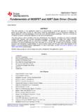
8 200nsguaranteed over the 40 C to 125 C operating junction temperature range. The LTC4441MP is guaranteed and tested over the full 55 C to 125 C operating junction temperature range. Note that the maximum ambient temperature consistent with these specifications is determined by specific operating conditions in conjunction with board layout, the rated package thermal impedance and other environmental factors. The junction temperature (TJ, in C) is calculated from the ambient temperature (TA, in C) and power dissipation (PD, in Watts) according to the formula: TJ = TA + (PD JA)where JA (in C/W) is the package thermal impedance. LTC4441/LTC4441-1444411faIN Pin Low Threshold Voltage vs TemperatureIN Pin High Threshold Voltage vs TemperatureEN Pin Input Threshold Voltage vs TemperatureTEMPERATURE ( C) 75 50IN PIN INPUT THRESHOLD (V)254441 G01 125 VIN = = 5 VTEMPERATURE ( C) 75 50IN PIN INPUT THRESHOLD (V)254441 G02 125 VIN = = 5 VTEMPERATURE ( C) 75 50EN PIN INPUT THRESHOLD VOLTAGE (V)254441 G03 125 VIN = = 5 VRISING EDGEFALLING EDGEFB Pin UVLO Threshold vs TemperatureSD Pin Input Threshold Voltage vs TemperatureDRVCC Voltage vs TemperatureTEMPERATURE ( C) 75 50FB PIN UVLO THRESHOLD VOLTAGE (V)254441 G04 125 VIN = EDGEFALLING EDGETEMPERATURE ( C) 75 50SD PIN INPUT THRESHOLD VOLTAGE (V)
9 254441 G05 125 RISING EDGEFALLING EDGEVIN = = 5 VTEMPERATURE ( C) 75 50 DRVCC VOLTAGE (V)254441 G06 125R1 = 330kR2 = 100kVIN = 25 VVIN = characTerisTicsNote 3: Failure to solder the Exposed Pad of the MSE package to the PC board will result in a thermal resistance much higher than 38 4: Supply current in normal operation is dominated by the current needed to charge and discharge the external power MOSFET gate. This current will vary with supply voltage, switching frequency and the external mosfets 5: Rise and fall times are measured using 10% and 90% levels. Delay times are measured from 50% of input to 20%/80% levels at Driver 6: Blanking time is measured from 50% of OUT leading edge to 10% of BLANK with a 1k pull-up at BLANK pin.
10 LTC4441 7: Guaranteed by design, not subject to 8: This IC includes overtemperature protection that is intended to protect the device during momentary overload conditions. The junction temperature will exceed 125 C when overtemperature protection is active. Continuous operation above the maximum operating junction temperature may impair device perForMance characTerisTicsLTC4441/LTC4441-1544411fa Typical perForMance characTerisTicsDRVCC Load RegulationDRVCC Line RegulationDRVCC Dropout Voltage vs TemperatureILOAD (mA)0 DRVCC (V)604441 G0720 120 140 160 180 200 VIN = = 25 CR1 = 330kR2 = 100kVIN (V)0 DRVCC (V)4441 = 25 CR1 = 330kR2 = 100kTEMPERATURE ( C) 75 50 DRVCC DROPOUT VOLTAGE (mV)254441 G09 2505010004003001002009008007006000500751 00 125 VIN = = 5 VILOAD = 40mAOUT Pin Pull-Down Resistance vs TemperaturetPLH, tPHL vs DRVCCtPLH, tPHL vs TemperaturetPLH, tPHL vs CLOADRISE/FALL Time vs DRVCCRISE/FALL Time vs TemperatureTEMPERATURE ( C) 75 50 OUT PIN PULL-DOWN RESISTANCE ( )